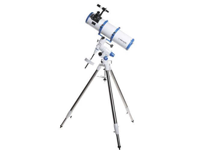
Looking to purchase a reflector telescope in Russia?
Our team of experts can guide you in choosing the ideal reflector telescope model.
We can also provide you with the latest information on product availability, payment options, and delivery terms specifically for customers in Russia.
Quick shipping
Convenient payment options
100% satisfaction guarantee
Astronomical Reflectors – telescopes with reflector technology
There are two main types of telescopes used for astronomy: refractor telescopes and reflector telescopes.
The first type, refractor telescopes, consist of glass lenses that are used as the objective and eyepiece.
On the other hand, reflector telescopes use a mirror as the main element to gather light from a specific area of space and focus it to a single point, similar to a lens.
Mirrored telescopes have been in use for a long time, with one of the earliest designs being proposed by Newton and still being used today.
The benefits of reflector telescopes compared to refractor telescopes
The term “refractus” in Latin, meaning “refracted”, accurately describes the function of a mirror lens, which is to refract (reflect) light at a specific angle.
In simpler devices, the mirror has a spherical shape that allows it to collect all incoming rays of light at a single focal point. In more advanced instruments, the mirror is shaped parabolically to eliminate optical distortions known as aberrations.
The advantages of a mirror lens stem from the physical differences between a glass lens and a mirror:
- A reflector gathers more light than even a well-designed lens;
- There is no chromatic aberration;
- There is a wide range of internal device designs that offer various geometric possibilities.
Receive expert guidance to your Email
We will provide recommendations on the top models of reflector telescopes available in Russia.
The primary configurations of reflector telescopes
One of the initial reflector telescope designs is Newton’s system, which aims to minimize distortion and direct light into the eyepiece or camera matrix.
Other mirror designs utilize a secondary mirror, typically spherical or parabolic, to collect light in the opposite direction and pass it through the first mirror via a central hole.
These constructions also come with several drawbacks, as they require sacrificing some of the lens’ light, not only due to the hole in the center, but also because of the partial shading caused by the second mirror.
Nevertheless, having two mirrors in the optical system enables not only the projection of the image in the correct area with the appropriate deviation (at a specific focus), but also the utilization of the second mirror for correcting distortions caused by the primary mirror.
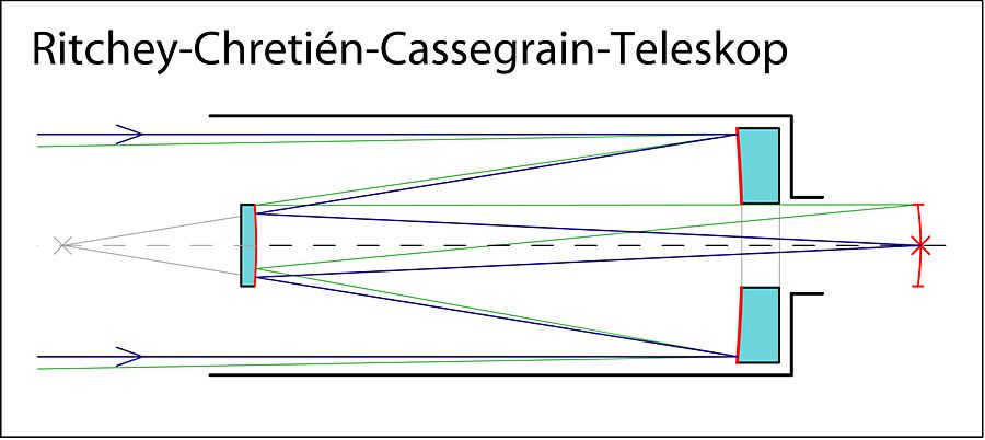
The Cassegrain system and the Cassegrain-Maksutov system are the most commonly used designs for reflector telescopes. These designs allow for the creation of high-quality and versatile devices by placing the second mirror between the main lens and its focus. This arrangement allows for a relatively small shielding of the main mirror within the compact dimensions of the tube.
The drawbacks of reflector telescopes are associated with the physical characteristics of the mirrors. The smoothness of a mirror’s surface cannot be achieved to the same extent as glass. Additionally, mirrors are susceptible to shape changes caused by fluctuations in temperature.
The primary disadvantages of telescopes that utilize a mirror lens can be summarized as follows:
- Distortions caused by imperfections in the reflective surface
- Deterioration of original properties over time
- Difficulty in securely positioning the mirrors
- Lack of protection for the main tube from atmospheric contaminants
- The need for complex adjustments and alignments
- Temperature fluctuations cause changes in the shape of objects.
To overcome the drawbacks of reflectors, advanced technologies and materials are being employed, which have expanded the range of applications for reflectors beyond their optical counterparts. Additionally, hybrid systems that combine mirrors and lenses are becoming more prevalent. Mirror-lens instruments are popular among amateur astronomers, while lens-based instruments are commonly designed for children and beginners. For professional deep space observation, reflectors are the preferred choice.
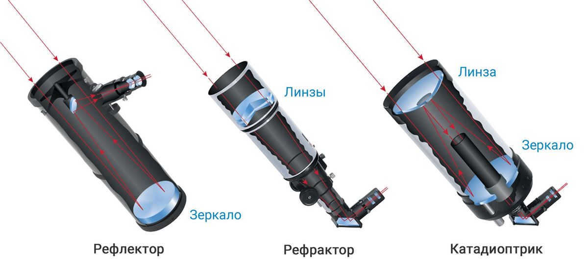
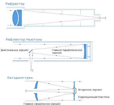
Refractors – telescopes that use lenses
Reflectors – telescopes that use mirrors
Catadioptrics – telescopes that use a combination of mirrors and lenses
Receive the blacklist of telescopes via email
We will provide you with information on which reflector telescopes – reflectors you should avoid purchasing.
Several Characteristics of Reflecting Telescopes
The primary and secondary mirrors of these instruments are either suspended on supports or mechanically fixed within the tube, depending on the specific design.
The mounting systems for these telescopes are constantly being enhanced. However, unlike refracting telescopes, this particular component is a vulnerable spot for reflectors. They are more sensitive to vibrations and transportation, requiring extra care and attention when handling.
Calibrating a reflecting telescope for optimal performance can also be slightly more challenging, necessitating a certain level of skill.
Nevertheless, despite the potential drawbacks of reflectors, they still remain the preferred choice for observing deep space objects with similar specifications.
The reflectors offer a significantly lower cost compared to other options, making it more affordable to purchase a high power device that meets the required parameters. Additionally, they are much more compact due to the ability to place mirrors.
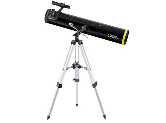
Looking to purchase a reflector telescope in Surgut?
Our team of experts can assist you in selecting the best reflector telescope models.
We can also provide you with the latest information on availability, payment options, and delivery terms for buyers in Surgut.
Quick delivery
Convenient payment options
100% satisfaction guarantee
Reflectors – reflecting telescopes
There are two main types of astronomical telescopes: refractors and reflectors.
The first type, refractors, are traditional telescopes that use glass lenses for all of their optical elements – the objective lens and the eyepiece.
A reflector, on the other hand, is a telescope that uses a mirror as its main element to gather light from a specific area in space and focus it to a single point, similar to how a lens works.
Mirrored astronomical instruments have been in existence for a long time. One of the variations that is still used today was first proposed by Newton.
The term “refractus”, derived from Latin, which means “refracted”, expresses the essence of the mirror lens, which operates by refracting (reflecting) light at a specific angle.
In simpler devices, the mirror has a spherical shape to gather all incoming light rays into a single point. In high-powered instruments, the mirror is parabolic in shape to eliminate optical distortions known as aberrations.
The advantages of a mirror lens arise from the physical differences between a glass lens and a mirror:
- A reflector gathers more light than even an illuminated lens;
- No chromatic aberration;
- It is possible to adjust the curvature of the mirror to customize the optical parameters to the desired values;
- There are numerous options for internal device designs in terms of geometry.
Receive expert advice via E-mail
We will provide recommendations on the most suitable mirror telescope models – reflectors in Surgut.
Key structures for reflector telescopes
One of the earliest reflector telescope designs, known as Newton’s system, was developed to minimize distortion and efficiently direct light towards the eyepiece or camera sensor.
Other mirror designs utilize a second mirror, also spherical or parabolic in shape, to collect light in the opposite direction from the first mirror. This light beam passes through the center hole of the first mirror.
There are also several drawbacks to such constructions, as they require sacrificing some of the lens’s light, not only due to the aperture in the center but also due to the shading caused by the second mirror.
Nevertheless, the inclusion of two mirrors in the optical system enables not only the projection of the image in the desired area with a specific deviation (at a particular focus), but also the utilization of the second mirror to rectify any distortions of the primary mirror.
The two most commonly used designs for reflector telescopes are the Cassegrain system and the Cassegrain-Maksutov system. These designs allow for the creation of high-quality and versatile devices by placing a second mirror between the main lens and its focus. This configuration enables a relatively small tube size and minimal shielding of the main mirror.
However, reflector telescopes do have some disadvantages due to the nature of mirrors. The surface of a mirror cannot be manufactured with the same level of smoothness as glass, and mirrors can also experience shape changes caused by temperature fluctuations.
The main drawbacks of telescopes using mirror lenses can be summarized as follows:
- Distortions caused by flaws in the reflective surface;
- Deterioration of original characteristics during use;
- Challenges in securely affixing mirrors in the desired position;
- Lack of protection for the main tube against atmospheric pollutants;
- The necessity for intricate calibrations and fine-tuning;
- Alterations in shape due to temperature fluctuations.
Optical designs of telescopes
Refractors – telescopes with lenses
Reflectors – telescopes that use mirrors
Catadioptrics – telescopes that combine mirrors and lenses
Subscribe to our E-mail list for the telescope blacklist
Discover which reflector telescopes – reflectors should be avoided.
Unique Features of Reflecting Telescopes
The primary and secondary mirrors of reflecting telescopes are either suspended on supports or mechanically fixed within the tube, depending on the specific design.
While mounting systems for these instruments are continuously improving, the reflector telescopes still have a potential weak point compared to refracting telescopes. Reflecting telescopes are less tolerant of vibrations and transportation, and require more careful handling. Therefore, it is essential to exercise caution when using a reflector telescope.
Additionally, adjusting a reflecting telescope for proper operation can be slightly more challenging and may require some skill.
Nevertheless, despite these potential disadvantages, reflecting telescopes are still superior for observing deep space objects with comparable parameters. The capability to observe these objects in greater detail makes reflecting telescopes the preferred choice in this type of telescope.
Reflectors offer a considerably lower cost, making it more affordable to obtain a powerful instrument with the necessary specifications. Additionally, their compact design allows for efficient mirror placement.
While modern astronomy relies primarily on large-scale instruments, smaller amateur telescopes have become increasingly capable of providing valuable information.
There are two main types of telescopes: refractors and reflectors.
The simplest refractor telescope is composed of a double-convex objective lens and a double-convex eyepiece. The lens gathers light rays from a source and focuses them into a point known as the focus. The focus then creates an actual image of the observed object, which can be magnified using the eyepiece.
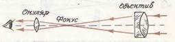
Refractor telescope: understanding the path of light rays.
When it comes to a telescope, there are two main functions it serves. The first one involves the use of the objective lens to capture light from distant celestial objects. The larger the size of the lens, the more light it can gather.
The second function is to provide a magnified view of the object under observation. What does this mean? The telescope’s focus creates an image of the celestial body, which is naturally much smaller than the actual object. However, this image is brought closer to the observer, allowing it to be viewed through the eyepiece at a significantly larger angle compared to what can be seen with the naked eye.
Thus, the magnification of a telescope refers to the ratio between the angle at which the image of an object is observed through the eyepiece and the angle at which the object would be seen with the naked eye. To calculate the magnification, it is necessary to know the focal lengths of both the lens and eyepiece. The magnification can be determined by dividing the focal length of the lens by the focal length of the eyepiece.
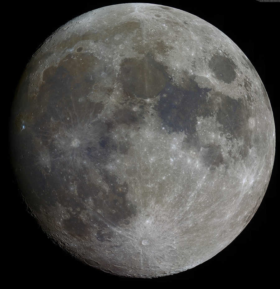
By using different eyepieces, it is possible to achieve varying levels of magnification. As the magnification increases, the field of view of the telescope decreases. For instance, at a magnification of 300x, you will be able to observe much finer details on the Moon compared to a magnification of 30x. However, the trade-off is that the field of view will encompass a much smaller area of the lunar surface.
If the observed object has a noticeable angular size (such as the Sun, Moon, planets, comets, nebulae, and galaxies), the telescope will create a magnified image, allowing you to detect details that are not visible to the naked eye.
However, this is not the case when observing stars. Even the nearest stars are located at such great distances from us that when viewed through the largest telescopes, as mentioned earlier, they still appear as mere dots. Therefore, telescopes do not enlarge the apparent size of stars, but they greatly enhance their apparent brightness.
Additionally, since stars have extremely small intrinsic sizes compared to the vast interstellar distances, telescopes increase the apparent distances between stars, making them appear farther apart. This can enable the observation of individual stars that would otherwise appear as single points of light to the naked eye.
Modern refractor telescopes rely on intricate optical systems to produce high-quality images. While a simple biconvex lens may seem like a logical choice, it actually comes with significant drawbacks. One of these drawbacks is known as spherical aberration. This phenomenon occurs when light rays from celestial objects passing through the lens fail to converge at a single focal point. As a result, it becomes impossible to achieve a uniformly sharp image across the entire field of view. If the center of the image is crisp, the edges will appear blurry, and vice versa.
One drawback is the occurrence of chromatic aberration. This issue arises because light emitted by celestial sources is composed of rays of different colors. When these rays pass through a lens, they are refracted and focused at different points along the telescope’s optical axis. In simpler terms, each color forms its own focal point. Consequently, the image of a point-like celestial object, such as a star, is heavily distorted. To counteract these aberrations, lenses must be made composite, requiring exceptional precision and presenting significant challenges.
For this reason, it is no coincidence that contemporary astronomy predominantly relies on telescopes utilizing concave mirrors in place of lenses. The first telescope of this kind was conceptualized and constructed by Isaac Newton in 1668.
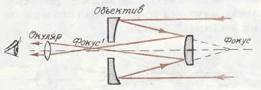
The path of the rays in a reflector telescope (one possible configuration).
Reflecting telescopes are not affected by chromatic aberration, as there is no dispersion of light when it reflects off the mirror surface. In order to correct for spherical aberration, the mirror is shaped into a parabolic curve. A parabolic surface has a unique property – it converges all parallel rays that fall on it to a single focal point.
The distance from the center of the lens to the main focus is known as the main focal length of the telescope, which is the point where a parallel beam of rays passing through the lens objective or reflected by the mirror intersects. This measurement is crucial in determining the performance of the telescope.
The ratio of the lens diameter to its principal focal length is referred to as the relative aperture of the lens. In photographic cameras, this is commonly known as the aperture. Lenses with a relative aperture ranging from 1:2 to 1:6 are considered fast lenses, as they enable the capturing of weakly illuminated celestial objects such as comets, nebulae, and star fields.
A typical medium-sized refractor telescope has an aperture of around 1:15, which indicates its ability to gather and focus light for observation.
The performance of a telescope is directly tied to the size of its objective lens. A larger lens area enables the observation of fainter stars using the same telescope. For example, a telescope with an 80 mm lens diameter can detect stars up to the 11th magnitude, while a telescope with a 760 mm lens diameter can detect stars up to the 16.2 magnitude.
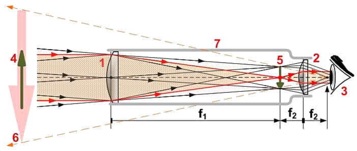
The Principle of Light Reflection in a Reflector Telescope
While a refractor telescope uses a system of lenses to create an image, a reflector telescope forms the image using rays reflected from a concave mirror. This type of telescope takes advantage of a geometric property of a parabola, specifically the fact that a beam of parallel lines to the axis of symmetryAFB of the parabola converge at a single point after reflection – the primary focusF (Fig. 57). By rotating the parabola around its axis of symmetry, a surface of rotation known as a paraboloid is obtained. The concave mirror of the reflector telescope, referred to as the primary mirror, is a section of this paraboloid surface, with the apex of the parabola located at the center of the mirror. By aligning the axis of symmetry with the celestial object being observed, its image is formed at the primary focus of the parabolic mirror.
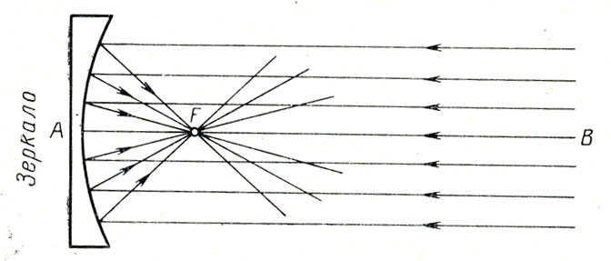
Figure 57. Rays from a parabolic mirror reflected
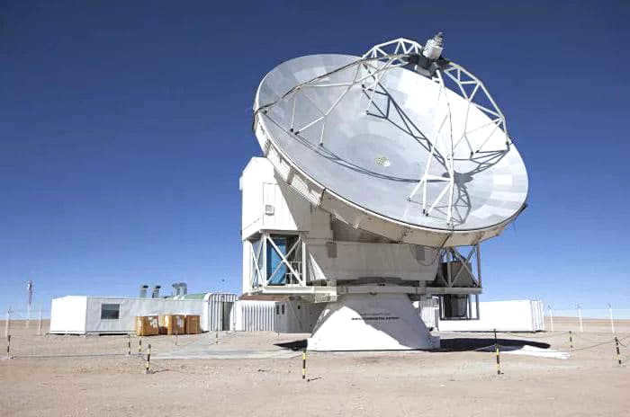
Radio telescopes are constructed based on this design. The mirror gathers radio waves, and at the focal point of the mirror, an antenna is positioned to receive the waves (Fig. 58).
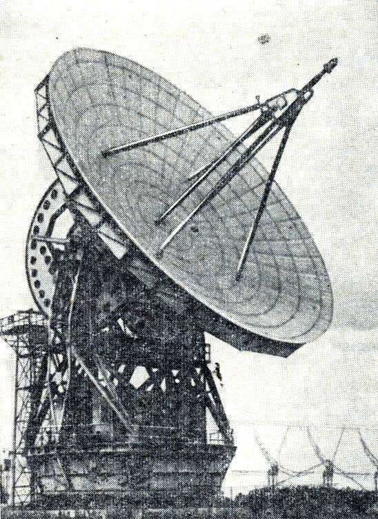

Figure 58. Radio telescope
The configuration of an optical telescope-reflector is rather intricate, as it is essential to redirect the rays out of the telescope tube for the purpose of observing and examining the image. This is achieved through various methods in different systems.
Newton is credited with inventing one of the most widely used systems. This system employs an inclined flat diagonal mirror to redirect the rays to the side (Fig. 59). Another popular system is the Cassegrain system (Fig. 60). In this system, the main mirror is manufactured with a hole drilled in the center, and then shaped into a paraboloid. A small hyperbolic-shaped mirror is placed on the main optical axis between the main mirror and its main focus. This small mirror reflects the incoming light into the center hole of the larger mirror, where the image of the observed object is formed.
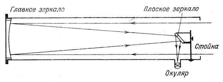
Figure 59 shows the path of rays in a Newtonian reflector telescope.
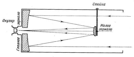
Fig. 60. Path of light rays in the reflector of the Cassegrain system
Reflectors offer numerous advantages over refractors. While making a parabolic mirror may not be a simple task, it is still much easier compared to crafting a lens. This is primarily because a mirror only has one surface, whereas a lens requires four. When it comes to constructing a lens, the quality of the optical glass used is of utmost importance. However, for a reflector, the quality of the glass is relatively inconsequential. In fact, many hobbyists have successfully created their own parabolic mirrors using glass disks sourced from portholes, which they then utilize for observations (Refer to the book “Telescope of an Amateur Astronomer” by M. S. Navashin, published by Fizmatgiz in 1967.) Unlike refractors, reflectors do not suffer from chromatic aberration and effectively transmit the colors of celestial bodies without any distortion.
Nevertheless, the reflector possesses a variety of notable drawbacks. Spherical aberration, for instance, stands out among them. Merely those beams that run parallel to the principal optical axis of the reflector converge at its primary focus into a single point. In the event that the beams are not parallel to the principal optical axis, there emerge pronounced distortions in the images, which are considerably more severe than those in a refractor. Consequently, the field of view without distortion is limited to merely a few minutes.
There is a second drawback associated with the requirement of silvering or aluminizing the mirror surface, as this coating tends to tarnish over time and needs to be refreshed periodically. The third drawback arises from occasional misalignment of the mirrors, necessitating readjustment of the reflector. However, the primary disadvantage of the reflector lies in its restricted field of view. Consequently, telescopes with more intricate combined systems have gained popularity in recent times.
One such optical system, known as a meniscus telescope, was created by the renowned Soviet optician D. D. Maksutov. This system utilizes a meniscus lens, which consists of two convexly curved spherical surfaces, to direct incoming rays towards a concave spherical mirror. The rays are then reflected towards the meniscus lens (Fig. 61), with a small aluminized spot on the inside of the lens reflecting the rays in the opposite direction. After passing through a central hole in the mirror, the rays form an image that can be captured through photography or observed using an eyepiece. The Maksutov meniscus telescope offers several advantages, including minimal chromatic aberration, a wide field of view, and a compact design. One example of this type of telescope is the MTO-1000 lens, which has a focal length of 1000 mm and is primarily used for photography. However, with the addition of an eyepiece, it can also function as a high-quality telescope.
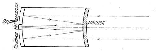
Fig. 61. Path of light in Maksutov’s telescope
astro-talks
forum for amateur astronomers
Path of light and beams in a telescope
Path of light and beams in a telescope
Message Ernest " October 18, 2014, 13:07
Diagram of the movement of light through the optics of a telescope
Opticians use the following abstract concepts to describe the movement of light through an optical system.
- A light ray is a vector that represents the direction in which light is propagating. When light travels through a uniform optical medium, it follows a straight path but changes direction when it encounters the boundaries of different optical media, in accordance with the laws of refraction and reflection. The light ray is always perpendicular to the front of light propagation. In diagrams, rays are typically depicted as thin, straight lines that indicate the direction of light. It’s important to note that a light ray is infinitely thin, and as a result, it carries an infinitesimal amount of energy from the light source to the point where it is absorbed, such as a photodetector.
- A light beam can be represented by a collection of light rays originating from a single point on the light source and potentially creating a single point of focus. The beam is typically confined in the transverse direction, with a finite cross-sectional area, and if the cross-section is symmetrical, it may possess a central axis known as the main ray. The other rays, excluding the main and aperture rays, are distinguished by their distance from the main ray, referred to as the zone (either angular or linear). Because of its finite size, a light beam can carry light energy, also known as light flux. Optical systems employ an aperture diaphragm to restrict the extent of light beams. When the rays of the beam (or their extensions) intersect, an actual or virtual image of a specific point on the depicted object is formed.
- The optical axis is the axis of symmetry for the rotation of optical systems that are considered centered. The centers of curvature of optical surfaces are located on the optical axis, and the axis intersects all optical surfaces perpendicularly. It serves as the primary reference point for measurements in the optical system, with all angles, apertures, fields, and transverse distances being measured from this axis.
- Aperture diaphragms are used to limit the size of light beams from the object, while field diaphragms restrict unnecessary light beams in their narrowest part, which is where the actual images are formed. Vignetting diaphragms partially limit light beams in the transverse direction.
- A meridional cross-section of a light beam is defined as the cross-section of a light beam that is created by a plane passing through the optical axis of a centered optical system.
- An object point refers to an elementary point on an object that has infinitesimal dimensions, and serves as the source of a collection of rays that form a light beam.
- The subject or object of observation is represented by a set of luminous points.
- The object space is defined as a set of all points that serve as real light sources, and are represented by the optical system. Typically, these points are located to the left of the first surface of the optical system along the path of the light.
- An image point is the point of intersection of the beam rays, which can be either real (allowing for the placement of an image receiver at this point) or imaginary (resulting from the intersection of retrograde extensions of the beam rays).
- The image of the object of observation is represented by a set of image points.
- Image space refers to the collection of all points, both real and imaginary, that are formed by an optical system after light beams pass through its final surface. Each point in the object space corresponds uniquely to a point in the image space.
- Parasitic rays and beams are those that should not have contributed to the formation of the image. They should have been blocked by apertures, absorbed by the housing and other components, scattered by defects in the optical surfaces and media, or deviated from their intended path. However, they still reach the photodetector, resulting in uniform illumination of the image and potentially causing focused flares.
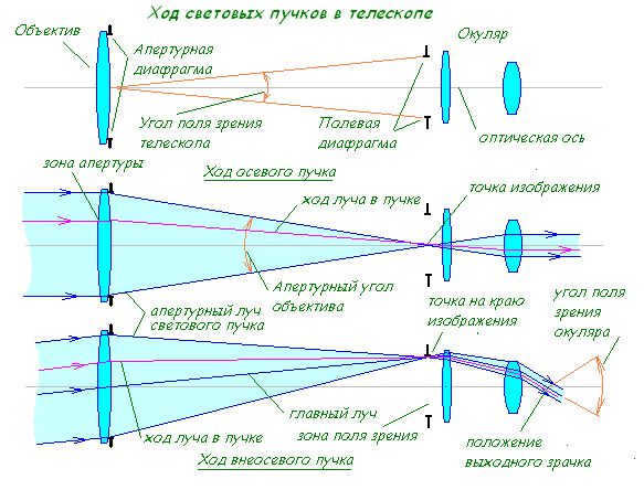
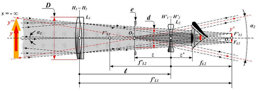
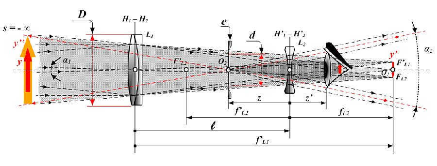
Now, let’s examine how these concepts are utilized to explain the transmission of light through a telescope, specifically a simplified refractor with a two-lens eyepiece.
[align=center][/align].
When illustrating optical schemes in domestic practice, it is customary to show a cross-section where the light from the objects being depicted comes from the left.
All points in the object space emit light in all directions. The telescope, which consists of multiple optical elements such as lenses and mirrors, is directed towards the object to observe. The telescope only captures a portion of the light emitted by each point in the object space, forming a beam of light rays that are practically parallel to each other (if the light source is located at “infinity”). This beam of light rays is limited by the aperture of the telescope, which in the figure is represented by the lens barrel.
Additionally, the light beam undergoes refraction and transitions from being practically parallel to essentially convergent as it moves towards the field diaphragm. In close proximity to the field diaphragm, the light beams are gathered and focused at specific points (each light beam has its own), creating an intermediate image. From these points in the intermediate image, the light beams then diverge, similar to how they would from real objects. However, there is one distinction – the points in the intermediate image only emit light within the limited range of the light beams defined by the aperture diaphragm on the lens. As the main rays of light beams pass through the field diaphragm, they have small angles with one another and with the optical axis, almost parallel, in other words, they move telecentrically.
Additional light rays are directed towards the optics of the eyepiece. By refracting through the eyepiece lens, these rays emerge parallel to other rays within their respective beams (although the beams themselves are not parallel to each other or to the optical axis). At the exit of the eyepiece, all the light beams (which consist of almost parallel rays) intersect at the area known as the exit pupil, where the image space is formed. In order to view a magnified image of the objects in space that the telescope captures, the observer’s eye (specifically, their pupil) must be positioned at the exit pupil of the telescope. This allows all the rays collected by the telescope to enter the eye and contribute to the formation of a real image on the retina (the layer of light-sensitive cells).
A few key points to consider:
- When light passes through a telescope, it forms a special beam known as the axial beam. This beam is symmetric around the optical axis of the telescope, meaning that all the rays in it rotate around the center axis.
- The lens of the telescope collects a beam of parallel rays from the axial point of an object that is infinitely distant. This collection point is called the back focus of the lens. Similarly, the front focus of the eyepiece is a point on the optical axis that forms a beam of strictly parallel rays when exiting the eyepiece.
- For the light beams, which are made up of parallel rays, to exit the telescope with parallel rays and form an image that can be viewed by the eye, the rear focus of the objective lens must be aligned with the front focus of the eyepiece. However, there are a few exceptions to this rule: (1) for individuals with nearsightedness, the light beams should be slightly divergent when they exit the telescope to compensate for the observer’s myopia; (2) when observing objects that are not at “infinity,” such as in terrestrial observations, the light beams that enter the telescope are not completely parallel, but rather divergent. In both of these cases, a small gap is needed between the back focus of the objective lens and the front focus of the eyepiece.
- Unlike the axial system, off-axis light beams that pass through a centered optical system do not exhibit rotational symmetry in relation to their central beam. However, it can be demonstrated that they possess perfect mirror symmetry in relation to a plane drawn through the optical axis and the main ray.
- By tracing the path of off-axis beams, we can observe their intersection at the point where the aperture diaphragm plane and the axis meet, as well as at the location of the exit pupil when the eyepiece is used. This means that the exit pupil is an image of the aperture diaphragm, since they are conjugate along the main rays. We can analyze two systems of light beams – the aperture beams that have been discussed previously, and a distinct axisymmetric beam of main off-axis beams. This particular beam is responsible for the conjugation of the entrance and exit apertures, as well as the entrance and exit pupil.
- When off-axis beams pass through the edge of the field diaphragm (as depicted in the lower fragment of the picture), they create an image of the edge or border of the field of view.
- The angular fields of view of the telescope are determined by the angles between the main rays of the extreme off-axis beams. The field of view of the telescope (TFOV – entrance field of view) is the angle between the main rays at the entrance to the telescope, while the exit field of view of the telescope (AFOV – apparent field of view) is the angle between the main rays at the exit from the telescope eyepiece.
- The convergence of the light beam is determined by the aperture angle, which is the angle between the outermost rays of one beam. The aperture angles are close to zero at the entrance and exit of the telescope (in this case, the aperture is more conveniently characterized by the beam diameter). Inside the telescope, the convergence of light beams is an important design characteristic that determines the level of difficulty in correcting aberrations of the telescope.
- Stigmatic light beams consist of rays that are either strictly parallel or intersect strictly at one point. When emitted from a single point of intersection, these light beams are fully stigmatic within the space of objects. However, once they pass through optical surfaces, the stigmatic property is lost as the rays can intersect with others at different points. This can result in the converging rays of the beam not strictly converging to a single point. These deviations from stigmatism are known as aberrations.
- There are some complicating factors that do not alter the aforementioned principles.
- Mirror telescopes use reflection to focus light beams, and typically have a central shielding zone surrounding the main ray. This zone does not contain any rays, and when describing these beams, we must also consider the rays that limit the shielding zone.
- When considering the reflection and reduction of an optical system, diagonal mirrors and prisms can be excluded while preserving the axisymmetry.
- To align the focal points of the eyepiece and lens, a Barlow lens, field corrector, or other pre-focal component can be added in front of the eyepiece. It is important to treat this component as part of the eyepiece or lens and calculate their combined focus, or alternatively, consider a cascade of three or more components to align their focal points.
- As a result of astigmatism, beams that are not aligned with the optical axis are focused at different points in the meridional and sagittal sections. These different points are known as astigmatic focuses, which is another example of how aberrations affect the optical system described above. The sagittal section refers to the cross-section of an off-axis beam that intersects with a plane that is perpendicular to the meridional section.
Return to the table of contents

The image quality of an observed object is determined by the type of telescope, its component parts, and the optical scheme it is equipped with. There are numerous optical schemes available for telescopes, which can be further classified into different types. Classical schemes are the preferred choice for most amateur astronomers, and we will discuss them in detail below.
Newton’s design is widely recognized as the most popular optical design. The Newtonian telescope operates using a flat diagonal mirror positioned near the focal point. The primary mirror, typically parabolic in shape, but can be spherical with a smaller relative aperture, reflects the light beam at a 45-degree angle, allowing for photography or viewing through an eyepiece.
Applications: Long-focus and short-focus Newtonian reflectors. Observation targets: Planets within the solar system. Advantages: Affordable price, lightweight, wide field of view, high magnification for observations. Disadvantages: Potential for spherical aberration, degradation of image quality over time, periodic realignment required.

Galileo’s Design Galileo’s design was developed based on a telescope that utilized a single collecting lens as the objective and a scattering lens as the eyepiece. One of the key advantages of this system is that the resulting image appears as if it were seen with the naked eye, meaning it is not inverted. However, there are also some drawbacks to this design, including a very limited field of view and significant chromatic aberration. Despite these limitations, the Galileo system is still considered to be an excellent choice for theater binoculars and DIY amateur telescopes.
Johannes Kepler once had the desire to enhance the performance of his refractor by substituting the dispersing lens in the eyepiece with a lens for collecting, and unexpectedly devised a novel system that was subsequently named after him – the Kepler’s optical scheme. The replacement of the lens allowed for a wider pupil and field of vision, but unfortunately resulted in an inverted image. The Kepler tube possesses an intermediate image, the plane of which can be furnished with a measuring scale. Hence, modern refractors are successors of the Kepler tube. The sole drawback of the system is its significant chromatic aberration, which can be easily remedied by employing an achromatic lens.
Application: refractors are used for observing the Moon, planets in the solar system, their satellites, and asteroids. Advantages: they offer a large field of view, provide high-quality images (in comparison to the Galileo system), and have a high magnification ratio. Disadvantages: the image is inverted and they suffer from significant chromatic aberrations.
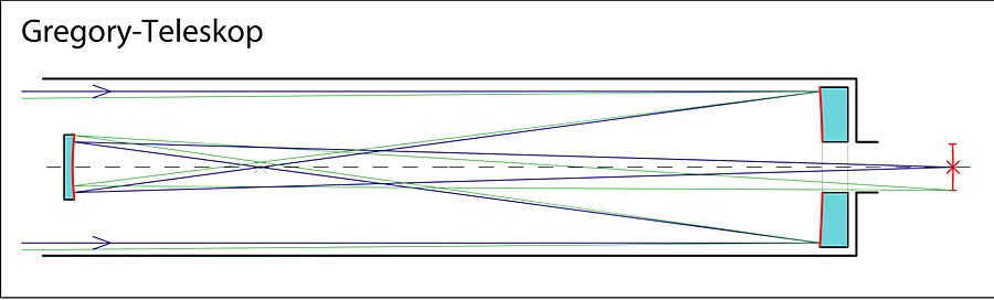
The Gregory optical design is a type of telescope that utilizes a main concave mirror with a parabolic shape to reflect the path of light rays onto a smaller elliptical mirror. The secondary mirror then redirects the light back to the central aperture where the eyepiece is located. Due to the shorter focal length compared to the distance between the mirrors, the resulting image of the observed object appears straight, making this design superior to Newton’s.
Applications: Reflecting telescopes
Objects of observation: Planets within the solar system, terrestrial objects
Advantages: High image magnification, long focal length, ability to capture photographs of celestial and terrestrial objects
Disadvantages: Lengthy tube, requirement for constant alignment, potential for excessive shielding, occurrence of thermal currents, heavy weight
How to Use: Reflectors What to Observe: Planets in the Solar System Advantages: Central shielding, High Image Quality Disadvantages: Issues with Direct Ray Protection, Image Aberrations at the Edges.
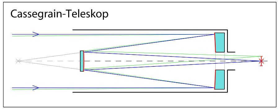
In the event that you enhance the design of the Cassegrain telescope, by substituting the primary parabolic mirror with a hyperbolic mirror, you have the ability to achieve a Ritchie-Cretien optical system where the field of view is approximately 4 degrees. This particular system is extensively utilized in the development of large-sized reflectors, as its primary advantage is the complete absence of coma, which enables the creation of high-quality astrophotography. The Ritchie-Cretien design, similar to the Cassegrain system, possesses an equivalent focal length that significantly exceeds the length of the tube. This design would be perfect for scenarios where moderate relative apertures are required for large-scale images.
Telescopes that detect ultraviolet radiation

When capturing photographs, ultraviolet rays can illuminate the photographic film. In certain parts of the ultraviolet spectrum, it is possible to capture images without any processing or backlighting. However, in some cases, it is necessary for the light rays to pass through a specialized filter. The use of filters helps to isolate specific areas of radiation.
There are different kinds of telescopes, each serving a specific purpose and possessing distinct features. These include X-ray and gamma-ray telescopes. Based on their intended use, all existing models can be categorized as either amateur or professional.
Mirror Instruments
Reflecting telescopes, also known as mirror telescopes, utilize a spherical mirror to gather and reflect light onto the eyepiece. Unlike lensed models, mirror instruments do not exhibit chromatic aberration since they do not refract light. However, they do have a noticeable spherical aberration, which limits their field of view.
Mirror models are easier to manufacture compared to their lens counterparts, making them more prevalent in the industry. The largest mirror telescopes have a diameter of over seventeen meters, with the largest one in Russia measuring six meters in diameter.

What is the structure of an optical telescope?
Every device, regardless of its design, has an eyepiece and a lens. The objective lens, which directly faces the observed celestial body, is referred to as the objective lens or mirror, while the smaller lens, where we “aim” with our eye, is known as the eyepiece. Both components are situated on the same optical axis as per convention.
In general, how does a telescope function? To observe objects that are nearby, it is necessary to periodically switch eyepieces. Typically, each telescope is equipped with at least two different eyepieces. These eyepieces allow the observer to adjust the magnification parameters using the same lens.
The telescope lens is designed in such a way that it becomes thicker as it gets closer to the middle, which is known as the collecting lens (symbolized by a “plus” sign). On the other hand, if the glass appears thinner in the middle, it is referred to as a scattering lens (symbolized by a “minus” sign). The optical axis is represented by an imaginary straight line that connects the centers of these lenses. When light rays travel parallel to this axis, they are refracted by the lens and converge at a specific point. A telescope lens with a significant curvature will result in a smaller focus, providing an image that closely resembles reality.
The device and operating principle


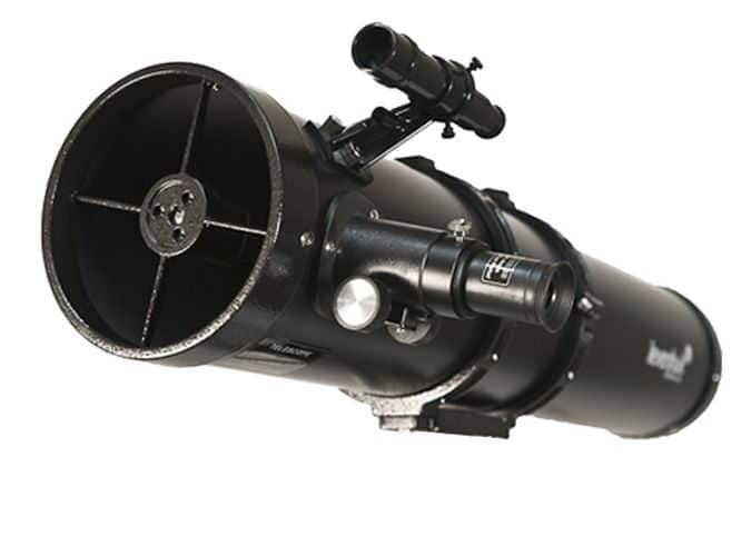
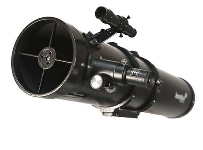
- The telescope tube serves as the main structural component, carrying the lens.
- The finder is a small telescope tube that is usually located on the same axis as the main tube. It is used for preliminary aiming at objects.
- The eyepiece is an interchangeable part of the telescope that is used for observing. Different eyepieces have different focal lengths, which affect magnification and viewing angle.
- Light filters are used to adjust the brightness of observed objects, such as the moon. They are not essential for beginning observations.
- Diagonal mirrors are utilized for observing objects at the zenith.
If you inquire, “How does a telescope function?”, two out of three individuals will likely inform you about amplifying objects and lenses. And they won’t be entirely accurate. Amplification, of course, is significant, but the high level of detail in observed objects is attained through light collection. The greater the primary light-gathering component of the telescope (either lens or mirror), the greater the level of detail of the observed celestial entity.

Refractors vs Reflectors
Telescopes that utilize lenses and rely on the phenomenon of light refraction are referred to as refractors.
The most notable refractors include the Pulkovo telescope, which boasts a lens diameter of 76 cm, and the York telescope, which features a lens diameter of 102 cm and a tube length of 21 m. Each refractor is equipped with two lenses.
It is worth noting that producing large, uniform, and precisely ground lenses is a complex technical challenge. As a result, mirrors are commonly used as lenses in astronomical telescopes. These telescopes are known as reflectors, with the largest one having a mirror diameter of 5 meters.
Reflectors are free from chromatic aberration.
To overcome spherical aberration, parabolic mirrors are employed. It is indeed a challenging task to manufacture a parabolic mirror.
Varieties of telescopes
*Refractors – they gather light through a lens and produce an image of the object at a focal point, which can be observed through the eyepiece. *Reflectors – they collect light using a concave mirror, which then reflects the light onto a small flat mirror and onto the surface of the telescope tube, where the image can be viewed. *Mirror-lens (catadioptric) – these telescopes utilize both lenses and mirrors in combination.
Peculiarities of working with telescopes
Optical Aberrations
When using a telescope under unsuitable conditions, where the instrument’s temperature does not match the surrounding temperature, and due to the unique characteristics of the optical system, distortions or defects in the image of the observed object may occur. These distortions can be rectified by using additional equipment. For instance, if a refractor telescope produces halos of specific colors around bright objects, it may be necessary to purchase a specialized corrective lens to address the issue. In some cases, reflector telescopes with a short focus may reflect objects with elongated shapes, resembling comets or pears. In such situations, experienced amateur astronomers often install a coma corrector in the telescope’s focuser to correct the aberration.
Achieving Thermal Equilibrium
Prior to operation, it is necessary to achieve thermal equilibrium for large refractors and catadioptric telescopes. The time required for temperature stabilization varies depending on the size and mass of the lens. Generally, the larger the lens and mass, the longer the telescope takes to reach thermal equilibrium. This phenomenon can be observed when the telescope is taken outside in cold weather. Since the equipment is initially warmer than the surrounding air, the lens may experience shaking due to the movement of air currents. Conversely, if the telescope is colder than the ambient temperature, undesired condensation may occur, resulting in a foggy lens and a blurry image of the observed object.
Right after purchasing a telescope, especially a reflector, every beginner astronomer will come across the phenomenon of alignment, which involves calibrating the optical device to achieve optimal quality. The alignment process essentially entails adjusting the tilt angle of the telescope mirror. Detailed instructions on how to perform this adjustment can be found in the user manual included with the instrument.
At our online store, we offer telescopes suitable for all levels of expertise and with various characteristics and features. Our managers are available to provide advice and assist with placing an order.
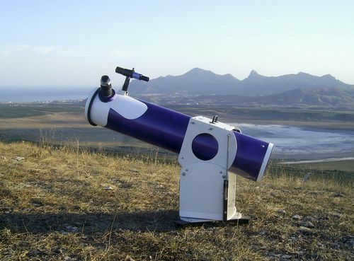
This article is written for amateur astronomers who have already experimented with binoculars and refractor telescopes, observed the phases of Venus, Saturn’s rings, and Jupiter’s satellites, and are looking for something more exciting and captivating. One example of such an exciting project is building a homemade telescope with a massive lens capable of magnifying objects up to 1000x. However, creating such a telescope solely with lenses is impossible due to a phenomenon called chromatic aberration, which causes rainbow halos to appear around objects, especially at higher magnifications.
Therefore, the solution is to construct a homemade reflector telescope, which utilizes mirrors instead. In its simplest form, this type of telescope consists of two mirrors (an objective mirror and a diagonal mirror) and one lens (ocular lens).
Where to find
The primary mirror-lens of the telescope-reflector is a crucial and demanding component. It is also the most challenging to acquire. Finding a pre-made mirror of this kind is nearly impossible.
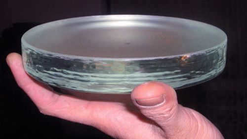
However, there is a solution: you can create one using a concave or convex-concave lens. Locate a large-sized concave or convex-curved lens. It is important for the focal length to be as long as possible, and consequently, the concavity should be minimal: excessively powerful concave lenses necessitate a parabolic shape instead of a spherical one, which presents a separate challenge that cannot be improvised.
To achieve the best results, it is recommended to search for a flat concave with a diameter ranging from 10 to12 cm and an optical power of 1 diopter at reputable optical stores. While this may not yield a telescope with a magnification of 1000x, it still offers potential for various applications.

Silvering with Chemistry
Next, the process of silvering needs to be carried out in order to create a mirror. The first step is to prepare a solution known as Tollens’ reagent. To make this reagent, you will require silver nitrate (also known as lapis), caustic soda (or caustic soda), and ammonia solution.
Formalin, which is a solution of formaldehyde, is also necessary to complete the preparation of this reagent. Dissolve 1 gram of silver nitrate in 10 milliliters of water, and dissolve 1 gram of caustic soda in another 10 milliliters of water. Combine these solutions, and a white precipitate will form. Add ammonia solution until the precipitate dissolves completely. This resulting solution is known as Tollens’ reagent.
To apply this reagent for the silvering process, it should be poured into a concave surface that has been thoroughly cleaned of any impurities beforehand. If the concavity is particularly weak, it is advisable to create a barrier along its edge using wax or plasticine.
To create a homemade reflector telescope, begin by pouring the reagent and then adding formalin to it in frequent drops. Over time, a film of silver will form and transform into a concave mirror. It’s important to note that the Tollens reagent should be used immediately after preparation and not stored for a long time.
There are alternative methods for creating a concave surface, such as grinding out a concave surface on glass circles. However, these techniques are quite complex and not recommended for beginners.
The same process should be followed to create a diagonal mirror. It should be perfectly straight, and any flat side of a flat-convex or flat-concave will work.
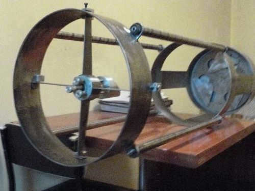

Putting the telescope together
Now you can begin the process of assembling the do-it-yourself telescope reflector. You will require a tube that matches the focal length of the mirror-lens precisely (if you utilized a flat-bent lens with a strength of 1 diopter, then use a tube that is 100 cm in length, with a correction of +0.5-1 cm to account for thickness).
The tube should be open on one end and closed on the other, with the interior painted using the darkest paint available. The diameter of the tube should be 1.25 times the diameter of the refractor mirror. For example, if you used a lens with a diameter of 100 mm, use a tube with a diameter of 125 mm.
Place the mirror-lens in the center of the tube, at the bottom. To facilitate this process, it is recommended to have a detachable bottom. One option is to secure the lens to the base using superglue.

Create a hole near the open end of the tube. To determine the appropriate position for the hole, measure the radius of the tube from the open end. The hole should be centered at that point. The eyepiece (perpendicular to the tube) will be secured in this hole.
It should be aligned with the optical axis at a 45-degree angle. If the angle is correct, you will be able to see the image when looking through the eyepiece. If it doesn’t work on the first try, experiment with the angle.
Explore more on our optical website:
- Guide on constructing a homemade telescope – diagram and instructionsThe era where anyone could make a groundbreaking scientific discovery is almost over. Everything that an amateur can uncover in the fields of chemistry, physics, and biology has already been studied, documented, and analyzed.
- Choosing the perfect telescope for a childReminiscing about my childhood always brings about a sense of nostalgia, as everything seemed so vast and distant, and I had a burning desire to learn and experiment. I can still recall my parents discussing different constellations and the North Star.